Plan smart home wiring before the renovation drawings are finalized. Mark the devices you want, identify their power and connection requirements, and agree on cable routes while the walls and ceilings are accessible. Give the electrician and low-voltage installer the same plan so outlets, network connections, and control wiring arrive at the right locations.
The biggest opportunities are usually the connections that will be difficult to add later: ceiling access points, outdoor cameras, concealed TV cables, and power for motorized shades. You can buy many of the devices later if their locations and supporting infrastructure are ready.
Map Devices and Cable Points on the Floor Plan
Start with the finished layout, including furniture, cabinetry, doors, and window treatments. A data outlet behind a future wardrobe or a camera cable ending above the wrong doorway is difficult to correct once the room is complete.
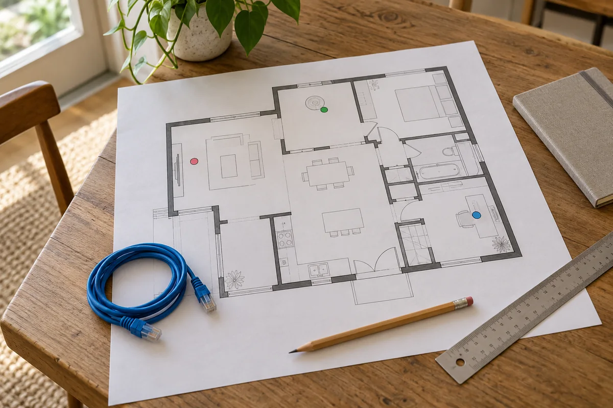
For each planned device, record its exact location, power source, connection type, and the equipment it connects to. Wireless control does not necessarily remove the need for a power cable or nearby outlet.
The following is an example planning schedule. Use it to build your own point list rather than treating every row as a requirement for every room.
| Planned location | What to record | Decision needed before installation |
|---|---|---|
| Ceiling Wi-Fi access point | Mounting position and Ethernet route to the network cabinet | Access-point model, coverage plan, and PoE requirements |
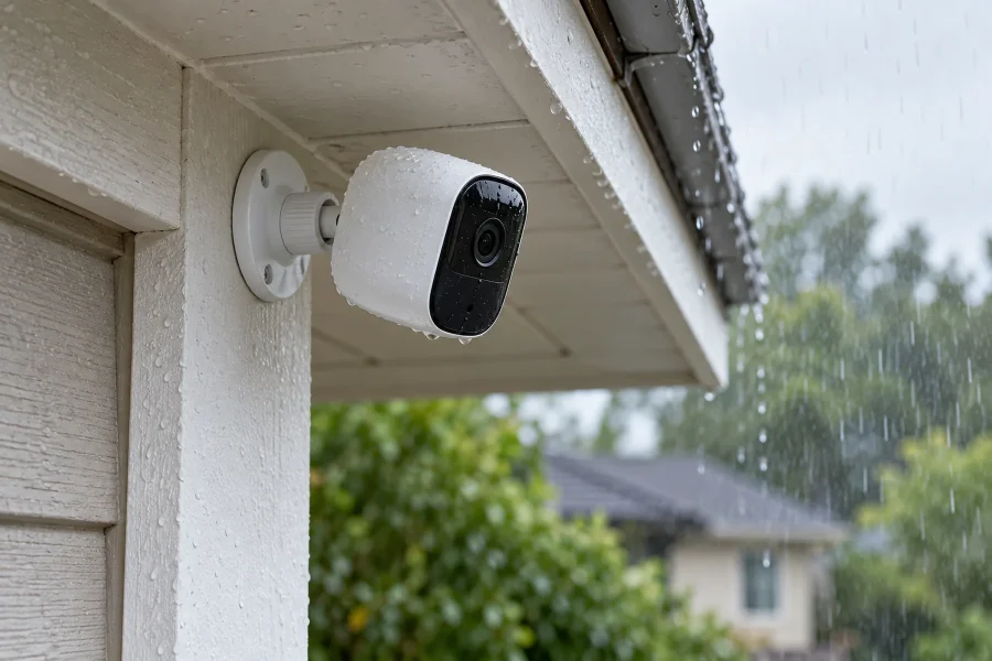
| Exterior camera | Viewing position, cable entry, and connection route | PoE, plug-in power, or battery operation |
| TV and media cabinet | Screen height, equipment position, outlets, and AV pathway | Where source devices and the receiver will sit |
| Home-office desk | Desk position, data outlets, and electrical outlets | Which computers or docks need wired connections |
| Motorized shade | Window identification, motor side, and power location | Motor system and its required cable or supply |
| Lighting control | Switch position, controlled fixture, and other control locations | Compatible switch or dimmer and wiring arrangement |
Include an alternative furniture arrangement where it is realistic. A second usable data point on another wall can be more valuable than several connections grouped behind one fixed cabinet.
Choose the Network Cabinet Location
Bring individual network cable runs back to an accessible distribution point, where a patch panel and network switch can connect them. Coordinate that location with the internet provider’s incoming service and modem or optical network terminal.
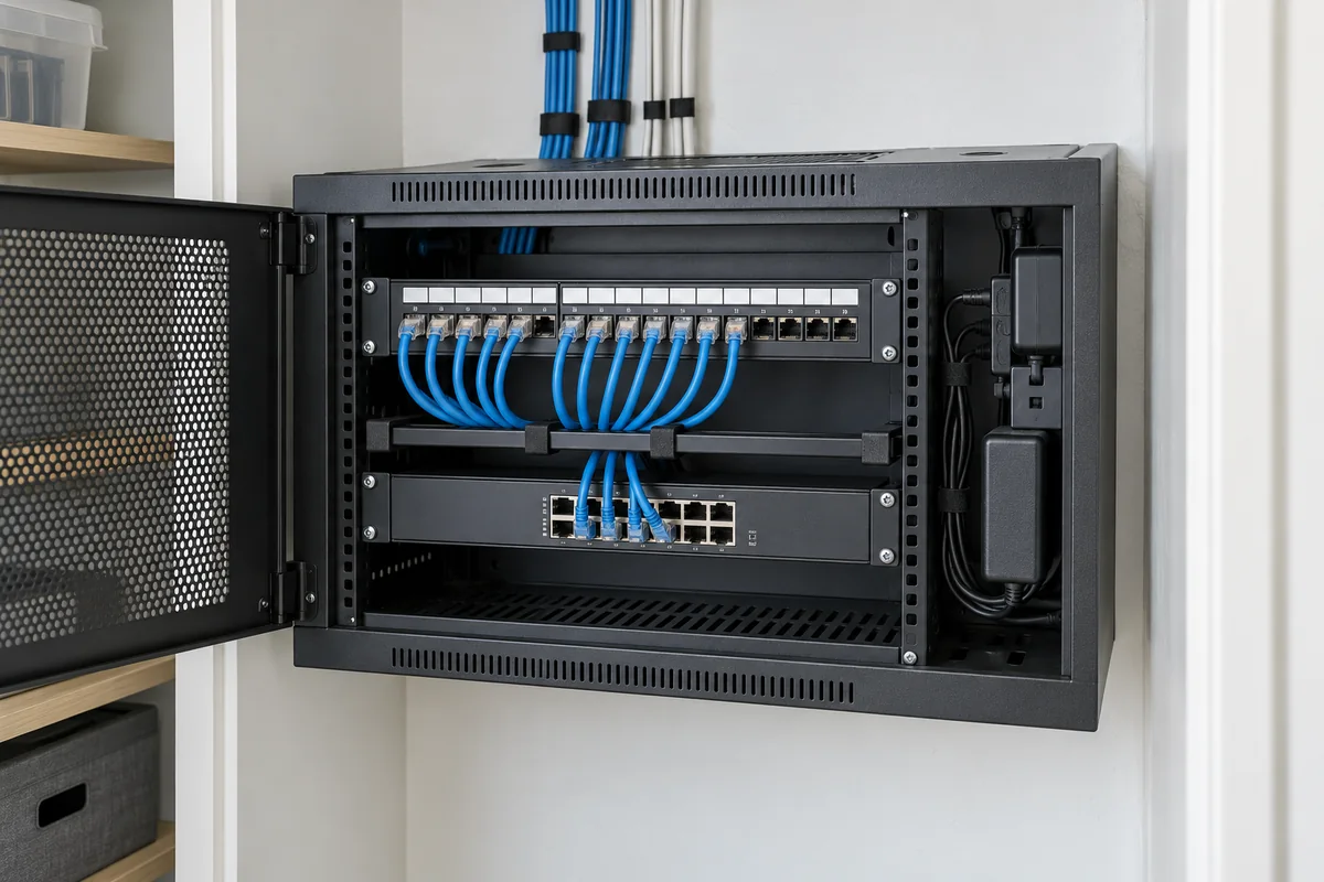
Draw the equipment layout before choosing an enclosure. Allow room for connectors, power adapters, cable management, ventilation, and access to individual ports. A shallow cabinet that fits the patch panel may still be unsuitable for a deeper switch or a collection of bulky power supplies.
Check the enclosure and equipment requirements together. For example, Leviton’s vented structured media enclosure is designed to provide airflow for active equipment. A larger installation may work better in an appropriately ventilated rack or equipment cupboard.
Have the electrician provide the required electrical supply. If you plan to add a UPS, include its dimensions and the equipment it will power in the layout. Leave enough access to replace it later.
The distribution point and the best Wi-Fi location may be different places. You can keep wired equipment together and place access points where the rooms need coverage.
Specify Ethernet Runs and PoE Equipment
Prioritize wired connections for access points, fixed cameras, desks, and media equipment that can use Ethernet. This gives those devices a defined network path and lets you position wireless coverage around the home.
Cat 6 or Cat 6A?
Compare the complete installed system, including cable, jacks, patch panels, termination, and testing. Category markings on the cable alone do not establish the performance of the finished link.
Cat 6 supports a 1 Gb/s Ethernet channel up to 100 meters. Cat 6A supports 10 Gb/s over a channel up to 100 meters, including the patch cords. Cat 6 can also support 10 Gb/s over shorter distances under suitable conditions; Belden’s copper cabling design guide explains these distance differences.
For new, difficult-to-replace runs, I would compare a Cat 6A installation with Cat 6 before accepting the quote. Keep serviceable existing cable where its tested performance meets the intended use. Cable upgrades do not increase the speed of an internet plan or device beyond its own capabilities.
Power over Ethernet
PoE lets compatible equipment receive power and data through the same Ethernet connection. It is useful for ceiling access points and cameras because a suitable PoE switch or injector can supply power from the network end. The Ethernet Alliance explains the technology in its PoE overview.
Record the power requirement of each device. The supplying port must support the required PoE type, and the switch must have enough total power available for the devices attached to it. A switch with sufficient ports can still have an insufficient power budget.
If a future camera has not been selected, document the intended location and leave an accessible, protected cable termination. Confirm the final camera, mounting, cable exposure, and weather-sealing requirements before installation.
Plan Wi-Fi Coverage Before Fixing Access-Point Positions
Mark proposed access points on the floor plan and consider the walls, floors, and areas they need to serve. Match the mounting orientation to the equipment. A ceiling-mounted design should not automatically be placed in a cupboard because that is where the cables are easiest to hide.
Where practical, provide a wired connection back to the network switch. Wireless mesh can help where cabling is unavailable, but the quality of its wireless backhaul becomes another dependency. Ubiquiti’s wireless performance guidance recommends wired connections to access points when possible.
Ask the network installer to assess coverage before finalizing the locations. Check it again after the renovation, when cabinetry, appliances, and furniture are in place. Avoid specifying one access point per floor as a universal rule; room layout and construction affect the design.
Confirm Wiring for Lighting, Thermostats, and Shades
These systems need decisions beyond adding an Ethernet outlet. Select the relevant controls early enough for the electrician and equipment supplier to confirm their requirements.
Smart Switches and Dimmers
Have the electrician check neutral availability, box capacity, the lighting load, and any circuit controlled from multiple locations. Some smart controls need a neutral connection, while others are designed to operate without one.
Lutron’s neutral-based dimmer guidance explains why its neutral-connected models can offer broader load compatibility and improved behavior with certain LEDs. Use the selected control’s documentation to establish the actual requirements.
If the remodel already includes replacing switch boxes or wiring, discuss the future control options before that work is completed. Keep normal wall operation in the plan so family members can use the lighting easily.
Smart Thermostats
Identify the heating and cooling equipment before choosing a thermostat. Check voltage, system type, control stages, and the thermostat’s power requirements.
For instance, Nest thermostat compatibility depends on the system and wiring; some installations need a C wire or an approved power accessory. Ethernet cable is not a general replacement for the thermostat cable specified by the equipment manufacturer.
Motorized Shades
Choose the motor and power approach before locating the supply. Depending on the system, a shade may use batteries, a nearby adapter, or a wired supply. Somfy’s motorized-shade power guide describes these different arrangements.
Confirm the motor side, cable specification, allowable run length, and access to the supply with the shade provider. Coordinate the exit point with the window trim and shade pocket so the final installation can conceal the connection without trapping serviceable components.
Plan Cable Routes and Future Access
Draw the routes as well as the endpoints. Identify how cables reach another floor, pass between rooms, or travel from a media cabinet to a wall-mounted screen.
An accessible conduit can be worthwhile where future replacement would otherwise require opening finished surfaces. CEDIA’s smart home wiring guide includes pathways and documentation among its planning priorities.
Ask the installer to size the pathway for the expected cables and connectors, allow appropriate bends, and provide accessible ends and a pull cord where suitable. A concealed tube is of limited value if a future connector cannot pass through it. For AV connections, plan the actual source-to-display route rather than assuming an Ethernet drop will carry every signal directly.
Specify cable suitable for each route. US communications-cable classifications include plenum, riser, and general-purpose types, as described by UL Solutions’ cable certification guidance. Outdoor exposure and other installation conditions also need to be addressed.
Have the electrician and low-voltage installer coordinate separation, supports, and penetrations using the applicable installation requirements. Where a route crosses fire-rated construction, preserving that assembly is part of the work; firestopping systems protect penetrations against the spread of fire and smoke.
Coordinate the Rough-In and Pre-Drywall Review
Agree on responsibilities before work begins: who installs each cable, who supplies the controls, who terminates and tests the network, and who arranges required inspections. Confirm local permit requirements for the actual work. ESFI’s electrical safety workbook explains why permits and inspections can be part of electrical alterations.
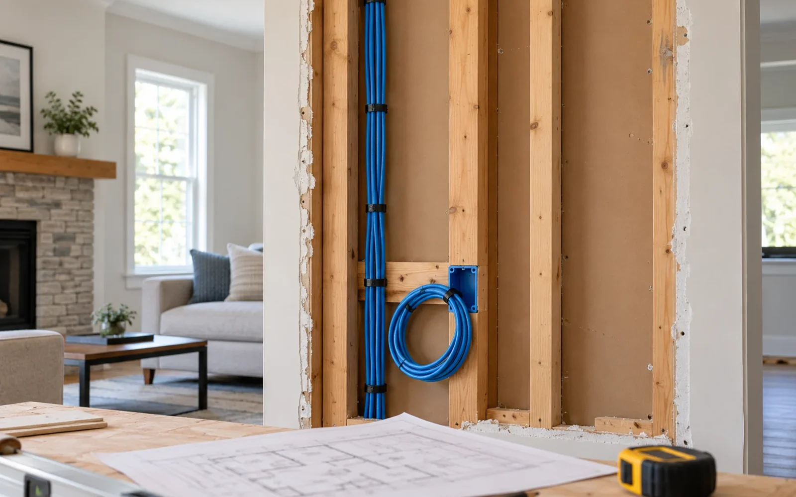
Once the cables are in place, walk the site with the installers and compare it with the point schedule. Before the walls and ceilings close, check that:
- Cable endpoints match the agreed furniture, equipment, and mounting locations.
- Both ends carry matching identifiers, including spare runs.
- Supplies and serviceable connections will remain accessible.
- Planned pathways, mounting provisions, and required inspections are complete.
- Cable routes are photographed and marked on the updated plan.
Use identifiers such as OFFICE-DATA-01 consistently on the outlet, cable, patch panel, and drawing. Photograph the routes with enough surrounding detail to identify the wall or ceiling later. Record changes made during construction rather than relying on the original drawing.
Test the Finished Installation and Keep the Results
Specify the required testing in the quote. A basic continuity test checks connections; it does not establish that a link meets a claimed cable category. Fluke Networks distinguishes verification, qualification, and certification testing, which answer different questions about a cable installation.
For a new installation sold as a specified category, request an appropriate test report for each completed link. Match the report identifiers to the patch panel and floor plan. Arrange suitable checks during rough-in, then final testing after termination and completion of work that could affect the cables.
Also verify operation at the intended device locations. Confirm that PoE devices start correctly, network outlets work, access points provide the intended coverage, and wall controls behave normally. Cable testing and device commissioning are separate parts of the handover.
Keep the final point schedule, drawings, photographs, test reports, and equipment list together. Ensure the household receives the necessary administrator access and knows which installer is responsible for any outstanding work.
Conclusion
For a limited remodel, I would prioritize an accessible network distribution point, Ethernet to the most useful fixed locations, and the power arrangements that will become difficult to change after finishing. Add well-planned pathways where future access matters. That gives you a practical foundation to expand from, with the locations, labels, and test results needed to use it confidently.

Ethan Miller
Ethan Miller writes about home improvement, interior design, cleaning, and everyday living at Home & Living Daily. He shares practical tips and simple ideas to help readers create more comfortable and functional homes.